Read Our Blog

Blog post 9

10-10-2022

IMechE UAS Challenge:

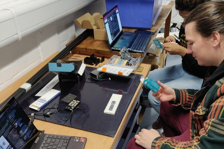
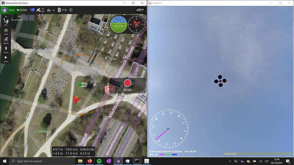
We’re branching out to enter the UAS challenge, which will kick off this month ending with a final fly-off event in June 2023. The challenge involves creating a fully autonomous drone which will complete a set of tasks, such as navigating to various waypoints, dropping a payload, and a specialised image recognition mission. The competition will also involve us creating a Ground Control System to interact with the drone and receive live telemetry and health data from the drone.

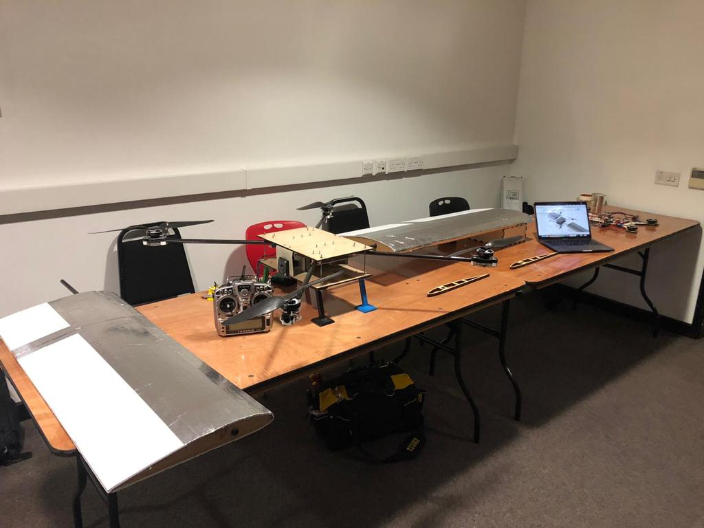
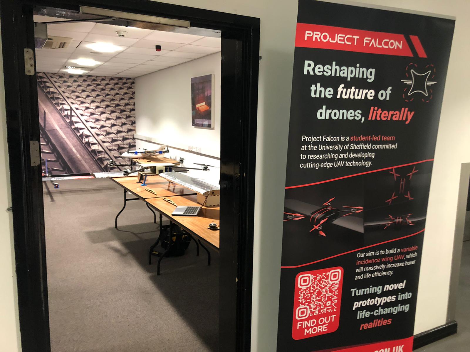
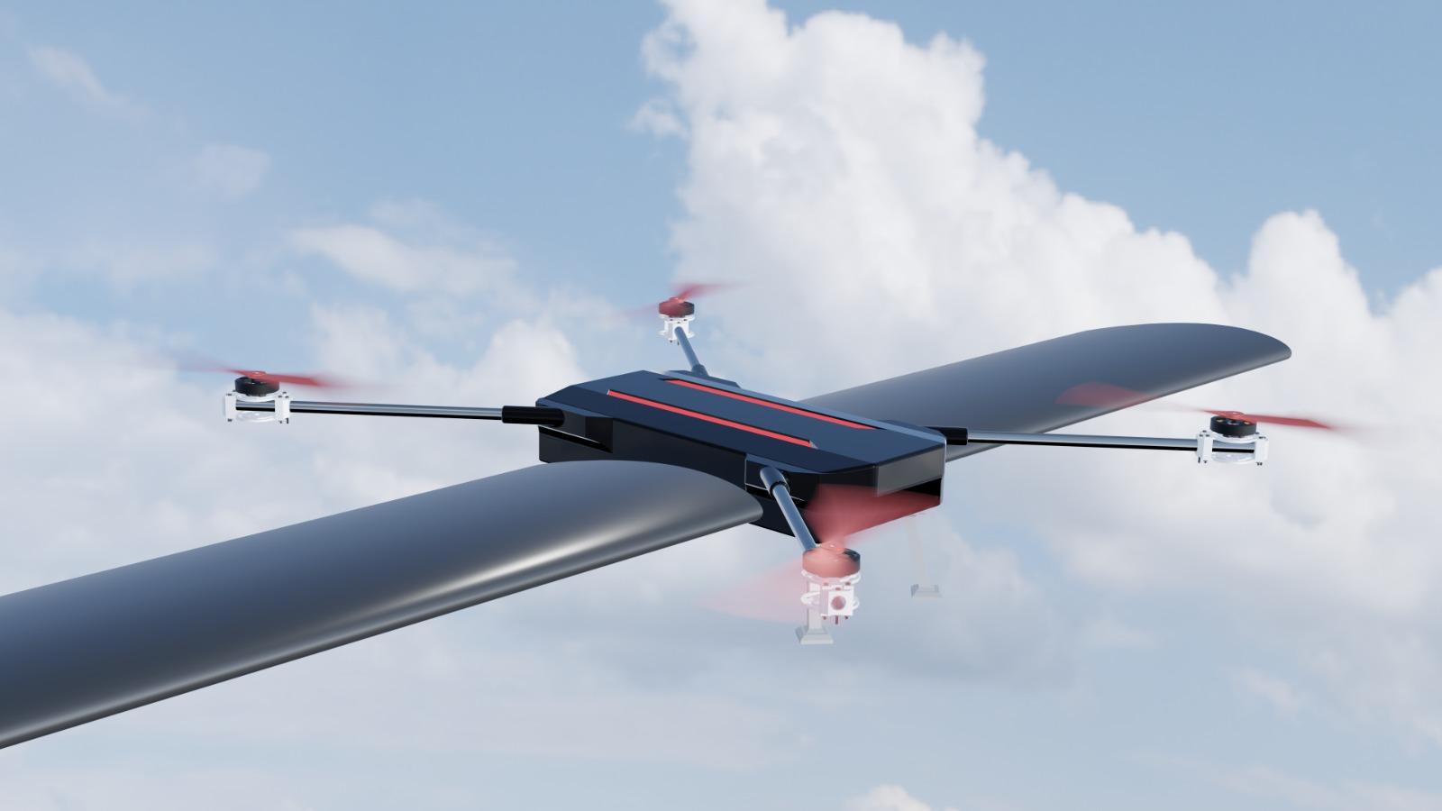
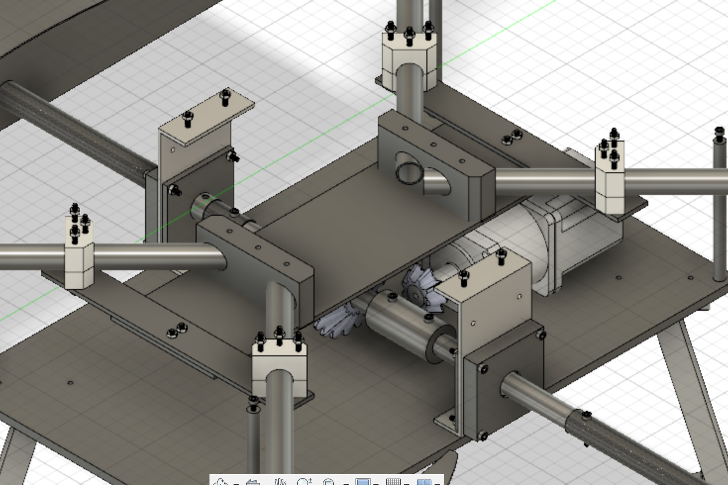
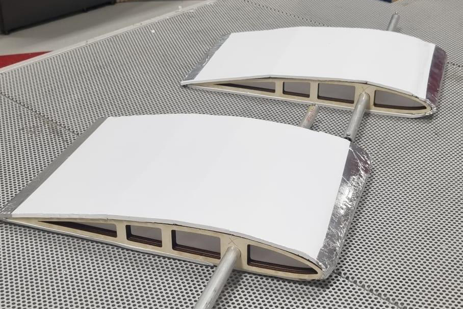
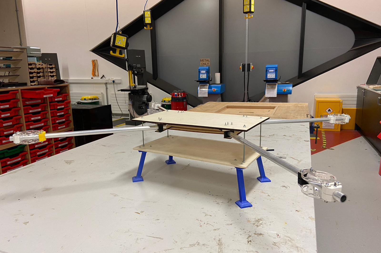
Variable Incidence Winged Drone:

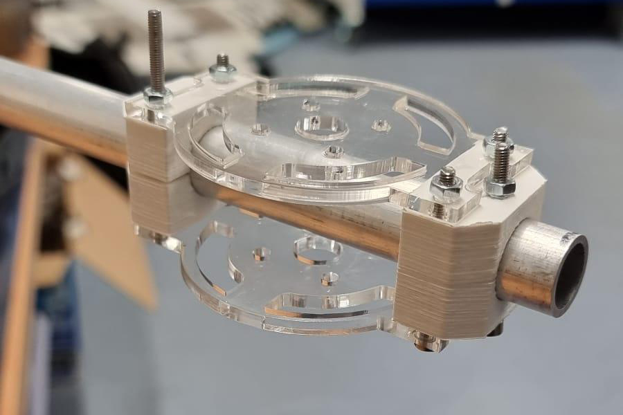
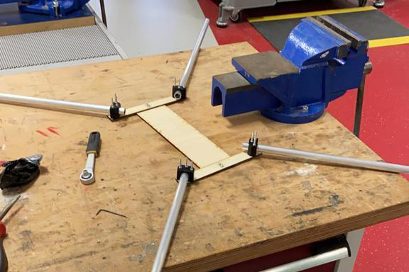
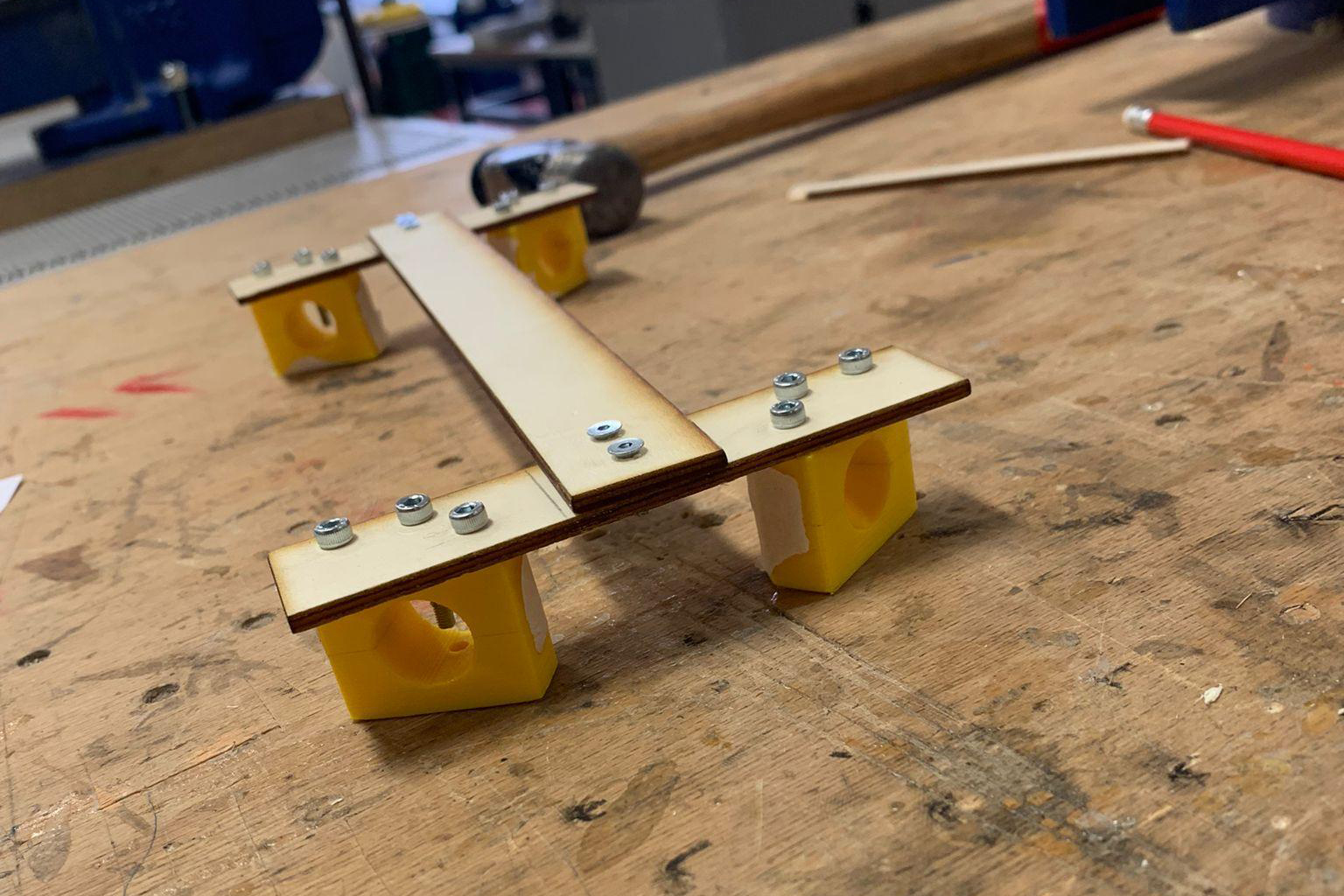
We planned to have Falcon’s maiden flight by September this year, however, we now anticipate this taking place in March 2023. We’re trying our best to fix our variable winged drone so we can get up and flying skyward, to start collecting data in the hope of writing a research paper on it in the future.
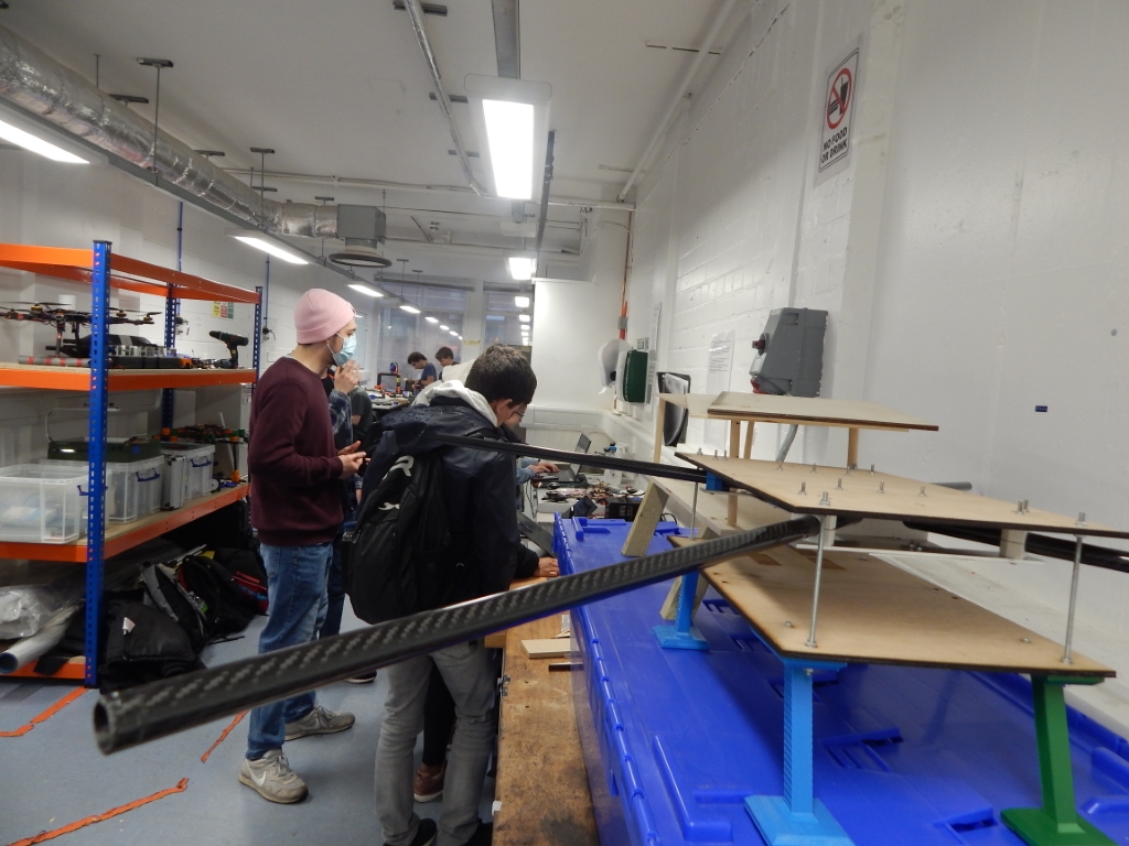
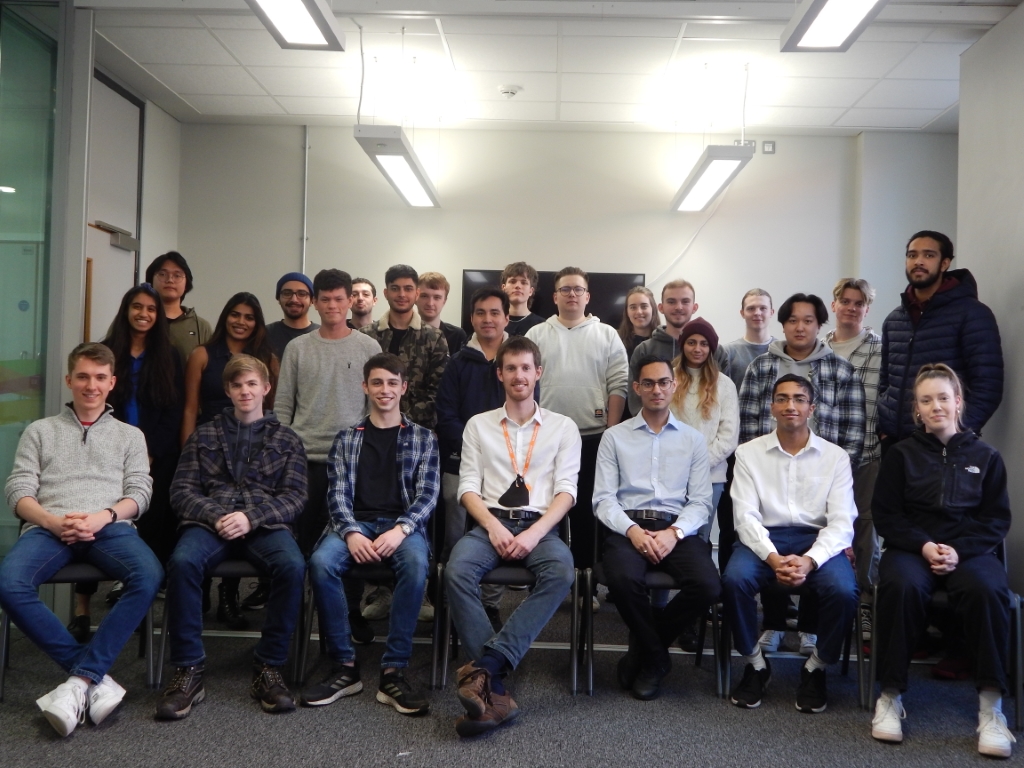
Team Updates:

Our aim is to split the sub teams (avionics/missions, flight dynamics and structures) so part of the team can focus on our research drone, whilst the rest can concentrate on our new competition drone. We’ve high hopes of beating teams from other participating universities across the country.

Blog post 8

09-05-2022

A photo of our drone and table at the Get Up To Speed event

A photo of our drone and table at the Get Up To Speed event

A photo of our banner and drone at the Get Up To Speed event

A photo of our banner and drone at the Get Up To Speed event

A photo of our drone and table at the Get Up To Speed event

A photo of our drone and table at the Get Up To Speed event

A photo of our banner and drone at the Get Up To Speed event

A photo of our banner and drone at the Get Up To Speed event

GUTS Review

The Get Up To Speed Event (GUTS) in Rotherham was aimed to introduce, inform and inspire students, parents, teachers and others from industry. Project Falcon were invited to attend the event to showcase our cutting edge technology that could revolutionise the aerospace industry in the near future. Across the day, we spoke to over 1,000 individuals, which wasn’t only great to spread the word but also showcase what Falcon is all about

As project lead, my job was to coordinate and manage the setting up of our stand as well as guide the conversations with those who visited us, ensuring we made the most of the opportunity.

How was preparation for GUTS and what did the team need to bring together?

The preparation of GUTS went fairly well, although we weren’t able to finish the drone to show functional wing control and a fairing. I believe we were able to pull through with an amazing display in the end, as the team brought the fuselage prototype, 2 finished wings, with one attached to the drone, the motors attached to a power supply to provide a live display as well as our finished avionics testbed complete with propellers.

What are the next steps for showcasing and developing the project?

We’re heading back to the workshop to continue working on the drone! Most of our attention is going to be focused on optimising the avionics systems, which will be an exciting time going forward. Ideally, the completed prototype will provide us with enough information and data to start the integration process and there’s hope to have Falcon’s maiden flight between June and September.

Blog post 7

14-03-2022

A prototype of our drone with the carbon fibre rods attached

A prototype of our drone with the carbon fibre rods attached

An updated team photo with our new members

An updated team photo with our new members

Our new Project Falcon caps

Our new Project Falcon caps

The Avionics team working hard in the lab

The Avionics team working hard in the lab

A prototype of our drone with the carbon fibre rods attached

A prototype of our drone with the carbon fibre rods attached

An updated team photo with our new members

An updated team photo with our new members

Chief Engineer Update:

With the completion of the test fuselage by the structures team, and finalising of the motor control system by the avionics team, electronics integration is the next big step in getting Falcon off the ground. Flight Dynamics are working tirelessly in the iForge to finish the final wing for our flying prototype.

Team Updates:

Since the start of the semester, we’ve expanded our team and are working on our new apparel. Having welcomed the new members, we’re continuing to work on developing the current aims as well as expanding our place in the community.

We’re looking forward to showcasing Falcon at the ‘Get Up To Speed’ exhibition later this month too.

Structures and Manufacturing:

Vacuum forming has been a huge part of our work over the last 6 weeks; the foam for the mould of the former has been constructed, and some parts for both the Avionics and Flight Dynamics team have been finalised. We’ll be pushing forward with the rest of the vacuum forming over the next few weeks. We have also started desinging a payload system, looking at different mechanisms for deployment. Working from the prototype gears from semester 1, we decided to optimse them further to manufacture a second prototype, these gears will be housed in a bespoke gearbox which is in the process of being manufactured.

Flight Dynamics:

It’s been a semester of lots of activity in Flight Dynamics; the biggest accomplishment is laser cutting all of the ribs in preparation for mounting them onto the spars. We’ve been working closely with the Structures team to support the introduction of foam into the drone chassis.

Avionics:

The motors are spinning! The avionics have been assembled onto the test bed and we’ve been testing via a power supply in the lab. We’ve been busy resolving some of our software issues and correcting the motor direction and orientation in preparation for mounting.

Blog post 6

17-12-2021

An aluminium I-Beam with our carbon fibre rods

An aluminium I-Beam with our carbon fibre rods

An Avionics systems layout mockup

An Avionics systems layout mockup

Our carbon fibre rods

Our carbon fibre rods

A design render of our drone

A design render of our drone

The team testing an aerofoil in our wind tunnel

The team testing an aerofoil in our wind tunnel

A chassis prototype with our carbon fibre rods

A chassis prototype with our carbon fibre rods

An aluminium I-Beam with our carbon fibre rods

An aluminium I-Beam with our carbon fibre rods

An Avionics systems layout mockup

An Avionics systems layout mockup

Structures and Manufacturing:

This week’s focus was on both collaboration with the Avionics team, to layout all the electrical components on the fuselage, and also manufacturing final parts assembling Beta-Test 5 (BT5). At this stage, carbon fibre was cut and it replaced the aluminium tubing used previously. Not to mention a new I-beam was constructed from aluminium, instead of wood which was used before.

Flight Dynamics:

The team went to the wind tunnel this week to test out the aerofoil that they built in week 10. The test concluded that the wings with the ribs wider apart proved much better and were more efficient, allowing the wing to be stable over higher airspeeds.

Avionics:

The team managed to finalise the radio connectivity between the receiver and controller. A couple minor bugs were also fixed regarding the Ardupilot software.

Blog post 5

03-12-2021

Cad model of the internals of our drone

Cad model of the internals of our drone

The battery storage cupboard

The battery storage cupboard

2 test aerofoils

2 test aerofoils

Our prototype with the motor brackets attatched to the chassis

Our prototype with the motor brackets attatched to the chassis

A CAD design for the c-clamp

A CAD design for the c-clamp

Our bearings

Our bearings

A larger 3D printed leg

A larger 3D printed leg

SLS printed gears

SLS printed gears

Cad model of the internals of our drone

Cad model of the internals of our drone

The battery storage cupboard

The battery storage cupboard

Structures and Manufacturing:

The structures team started researching a possible payload design, but as a team, we decided it was better to focus on finishing and finalising Beta-Test 4 (BT4), rather than starting to design a completely new system. The week’s main focus was on wing assembly and collaborating with the Flight Dynamics team on how this would work. We designed C-brackets, bearing mounts and a prototype bevel gears assembly for the wing-assembly.

Flight Dynamics:

The Flight Dynamics team spent the majority of the past two weeks in the iForge building the first prototype aerofoil. They built two wings, with different rib spacings, in hope of testing them in the University's wind tunnel.

Avionics:

The main tasks these weeks were to set up battery charging stations and locations to safely store them. This was of high importance due to the strict regulations the University enforced.

Blog post 4

19-11-2021

The Avionics team programming using the Pixhawk

The Avionics team programming using the Pixhawk

3D printed and laser cut motor brackets

3D printed and laser cut motor brackets

A plywood I-Beam fitted with aluminium rods

A plywood I-Beam fitted with aluminium rods

A plywood I-Beam with the 3D printed motor clips

A plywood I-Beam with the 3D printed motor clips

A sketch for the gearbox

A sketch for the gearbox

Our remote controller

Our remote controller

A circuit board for the Avionics team

A circuit board for the Avionics team

The Avionics team programming using the Pixhawk

The Avionics team programming using the Pixhawk

3D printed and laser cut motor brackets

3D printed and laser cut motor brackets

Structures and Manufacturing:

Beta-Test 3 (BT3) was manufactured with threaded rods to measure the stress the top sheet can withstand. The team then realised an I-beam is necessary to maintain load capacity on the fuselage. Hence, an I-beam was developed for the upcoming Beta-Test 4 (BT4). Additionally, the aluminium tubes were attached, acting as arms, to the i-beam through a new mounting system; the motor mounts were also attached to the arms. To increase the modularity of the design, solids rods and tubes were used to hold together both the spars through the bevel gears.

Flight Dynamics:

Further calculations were made to make sure that the aerofoil would be fit for the task. The team also ordered dephron to construct the prototype wing with, as well as some plywood which would be used to create the ribs.

Avionics:

All the new equipment and parts which the Avionics team ordered arrived and they spent the time setting it all up, as well as running standard scripts to upgrade firmware and test out the parts.

Blog post 3

05-11-2021

Our first prototype of the drone with the legs

Our first prototype of the drone with the legs

The first set of 3D printed motor bracket clips

The first set of 3D printed motor bracket clips

The Pixhawk controller

The Pixhawk controller

The Avionics team programming an Arduino

The Avionics team programming an Arduino

Our first prototype of the drone with the legs

Our first prototype of the drone with the legs

The first set of 3D printed motor bracket clips

The first set of 3D printed motor bracket clips

Structures and Manufacturing:

Both the motor mounts and legs were printed and tested for their structural integrity. Gears were also prototyped as the team found out they were necessary to transform the rotating force on the motor to the wing for wing rotation. Beta-Test 1 (BT1) was manufactured to test our original concept and Beta-Type 2 (BT2) to test a similar concept but adding an additional level.

Flight Dynamics:

The team eventually came to a decision to choose an aerofoil which would fit with our drone the best. The next steps were to calculate the forces which would be exerted on the rest of the drone and how the stepper motor would cope with the moments exerted.

Avionics:

The team focused on purchasing various parts and components, as well as learning about telemetry and how to collect it using the Pixhawk device we have.

Blog post 2

22-10-2021

A closeup photo of the motors

A closeup photo of the motors

The first set of 3D printed legs

The first set of 3D printed legs

A CAD design for a motor bracket

A CAD design for a motor bracket

The first set of 3D printed bearing mounts

The first set of 3D printed bearing mounts

A closeup photo of the motors

A closeup photo of the motors

The first set of 3D printed legs

The first set of 3D printed legs

Structures and Manufacturing:

Each team member was delegated a specific part of the design, which included motor mounts, bearings, wing spar, arms, and legs. They were tasked to design their part on CAD, and think about future prototyping.

Flight Dynamics:

During the last two weeks the Flight Dynamics team started researching the most optimal and efficient aerofoil shape for the drone.

Avionics:

These two weeks were used for conducting research into various electronic components such as the accelerometer. More research was put into the batteries and stepper motors we will use, as well as suppliers for high-quality radio components.

Blog post 1

08-10-2021

The Ardupilot software

The Ardupilot software

A brief sketch of a potential body design

A brief sketch of a potential body design

A brief sketch of a potential leg design

A brief sketch of a potential leg design

The Ardupilot software

The Ardupilot software

A brief sketch of a potential body design

A brief sketch of a potential body design

Structures and Manufacturing:

The team started off with concept development, which involved both hand-sketching and initial CAD designs on Fusion 360.

Flight Dynamics:

Over the first two weeks the team learnt Javafoil, an industry standard software used to analyse various aerofoils.

Avionics:

The Avionics team started research into Ardupilot and Mission Planner, the software which we’ll be using to control and manoeuvre the drone. They also researched various different techniques and ways we can control our variable incidence wing, finalising on using a stepper motor.